
Power system
Everything electrical lives in the locked cabinet. You will open it to flip breakers and read the display; anything beyond that is a job for VanBelkum or a qualified electrician.
PV = solar. PV stands for photovoltaic: panels that turn sunlight into electricity. Wherever this guide or a label in the cabinet says PV, it means the solar panels.
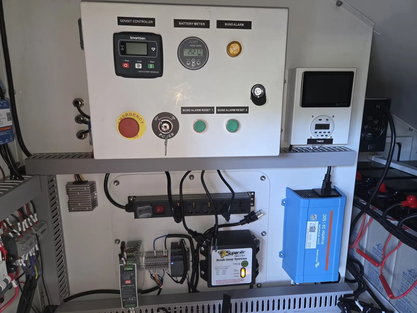
How the system is laid out
| Part | What it does |
|---|---|
| Four 450 W solar (PV) panels | Charge the batteries whenever there is daylight. |
| MPPT solar charge controller | Converts panel output to the right charging voltage for the batteries. |
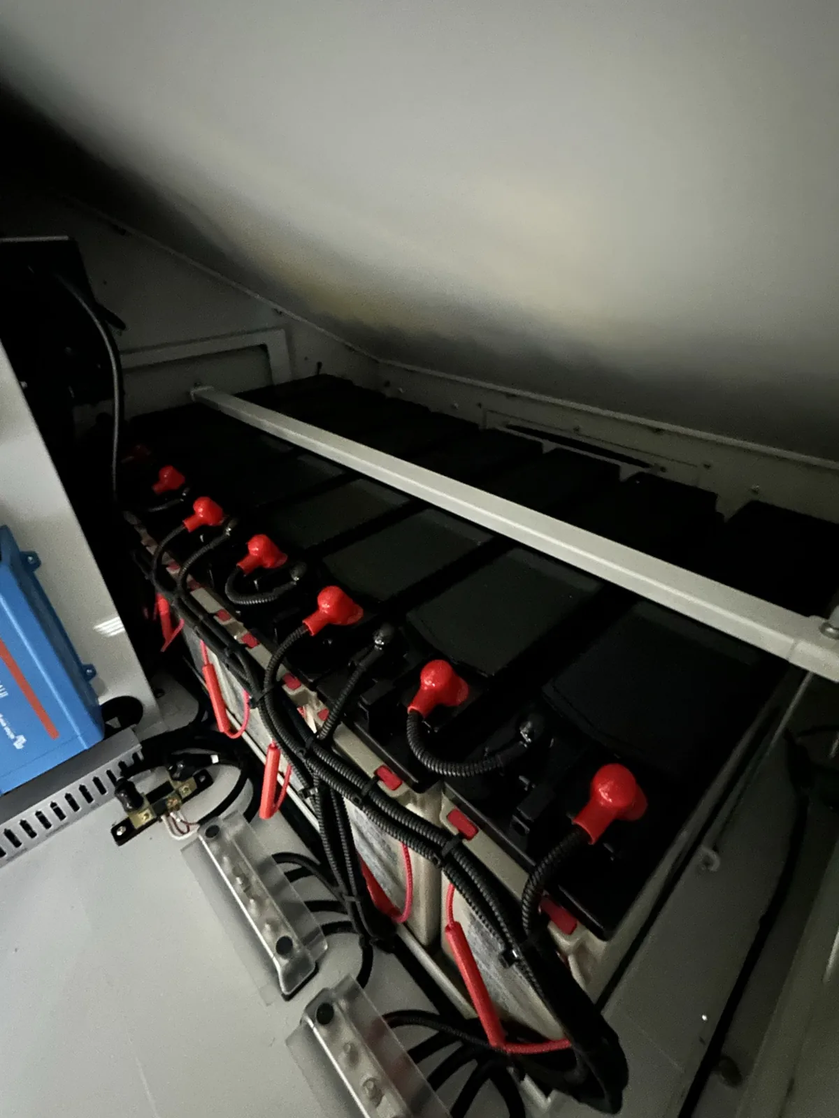
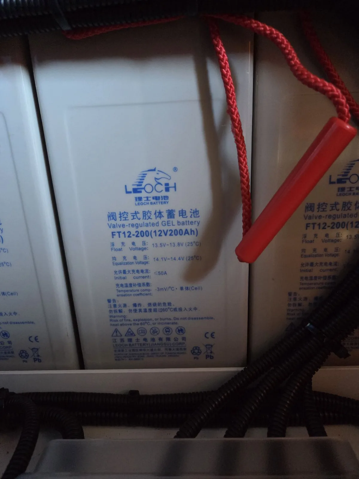
| Battery bank, 24 V | Eight sealed gel lead-acid batteries, 12 V 200 Ah each, wired for 24 V: 800 Ah, 19.2 kWh nominal. |
| Battery monitor | Tracks charge, voltage, and current through a shunt on the battery negative. |
| System controller with touch display | The screen on the back wall of the cabinet, under a clear cover. Shows solar, battery, and load in real time and connects the trailer to the remote dashboard. |
| Inverter and 120 V outlet | A 500 W inverter feeds a standard household outlet on the cabinet for small tools or a laptop. |
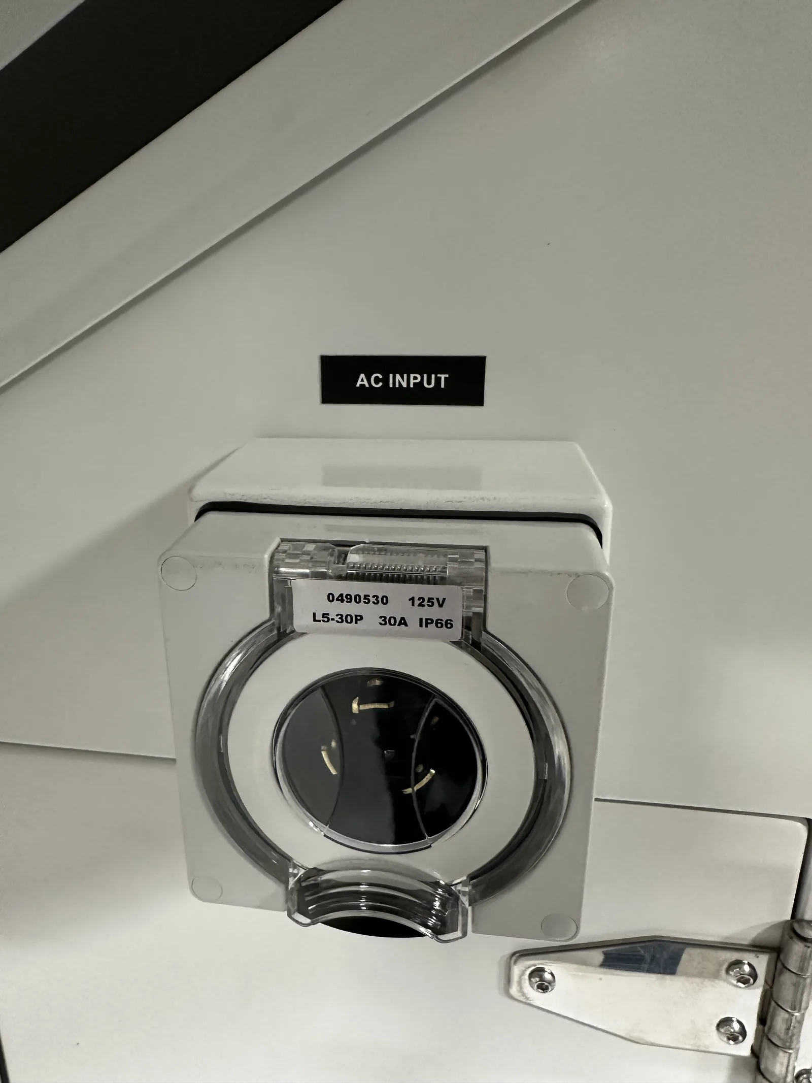
| Shore-power input | A 30 A twist-lock inlet for charging from mains power. An adapter cord to a standard 110 V plug is not included; ask VanBelkum for one. |
| DC converters | Feed the camera network switch and the 12 V accessories such as strobes. |
The breakers
The rail carries one breaker per circuit. Typical layout, left to right; the labels inside your cabinet are the authority:
| Breaker | Circuit |
|---|---|
| PV | Solar (photovoltaic) panels to the charge controller |
| Battery | Battery bank to the main bus |
| Inverter | The inverter that feeds the 120 V outlet |
| Cerbo GX | System controller and touch display |
| DC56V | Power to the camera network switch |
| Strobe Light (three) | The strobes at the mast head |
| Output Socket | The 120 V outlet |
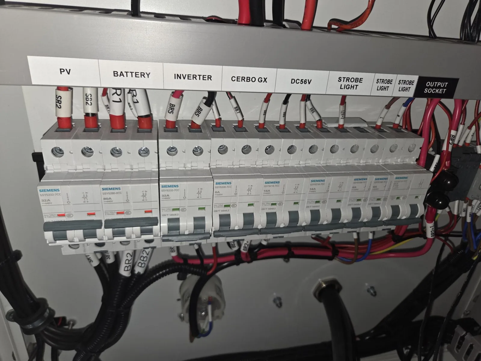
Normal operation: PV and Battery on, then Cerbo GX, DC56V, and any accessories you use. On these breakers red means on and green means off, the reverse of a house panel. To shut down, or before long storage: turn the load breakers off first, then PV, then Battery.
Only a qualified electrician should troubleshoot or repair the electrical system. Before any service, turn off the solar, battery, and camera breakers and disconnect the panels and batteries. Never take power directly from the battery terminals, and never lay metal tools on them.
The touch display and the app
The display inside the cabinet shows solar watts coming in, battery voltage and state of charge, and what the loads are drawing. The same data is available on your phone:
- Install the VictronConnect app.
- Stand near the cabinet with the breakers on. The controller’s indicator flashes while it is discoverable.
- Connect to the charge controller or the system controller. The charge controller’s default PIN is 000000; if that fails, the PIN is printed on the device. The system controller’s PIN is on its label.
- Once the system controller is online over cellular, the same numbers appear on the remote dashboard from anywhere.
Keeping it charged
The array covers a two-to-four-camera load comfortably from spring through fall in Michigan. Winter deployments, or a full load of cameras, lights, and speakers, may need a periodic top-up.
- Watch the dashboard. It tracks charge level, solar input, and draw. Set an alert for a low-battery threshold so you plan ahead instead of reacting.
- Top up from shore power. The inlet on the cabinet is a 30 A twist-lock. It needs an adapter cord to plug into a standard 110 V outlet, and that cord is not included; VanBelkum can supply one. The batteries charge while the trailer keeps running.
- Or from the generator. Trailers with the onboard generator start it automatically at a low-battery voltage and stop it when the bank is full. See the Generator page.
The outlet
The outlet on the cabinet is fed by a 500 W inverter. Use it for a laptop, a phone charger, or a small tool. It is not sized for heaters, compressors, or anything with a motor larger than a drill.
If the trailer will sit unused for a long time, turn the battery breaker off. A slow drain over weeks can take the bank below where it can recover.