
Set up on site
The order matters. Level the trailer first, deploy the panels second, and only then power the system. The mast comes after all of this, on the next page.
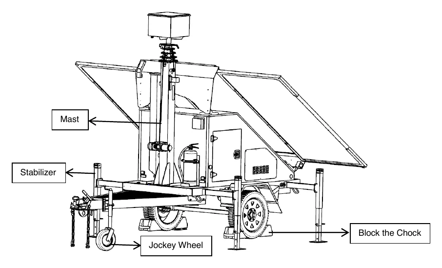
1. Position and chock
- Place the trailer on firm, relatively flat ground with open sky above it.
- Set the hand brake and put the wheel chocks against the tires so the trailer cannot roll. The hand brake is the lever on the tongue just behind the coupler; pull it up to set it.
- Pull the locking pin on the jockey wheel, rotate the wheel down 90° until the spring pin snaps back in, then wind the jack handle counter-clockwise to lift the drawbar off the tow vehicle. Unhitch, and move the vehicle clear.
The mast extends up to about 24 feet (7.5 m). Before you go any further, look up. The area above the trailer must be open and clear of overhead wires and obstructions.
2. Extend the outriggers and level
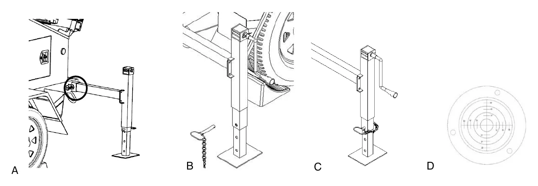
- Pull the locking pin on an outrigger and slide the arm out until the pin snaps back into place (A).
- Pull the pin at the bottom of the outrigger and refit it in the third hole up (B).
- Repeat for the other three outriggers.
- Wind each jack handle clockwise until the foot is firmly on the ground (C). Work around all four, a little at a time, until the bubble level on the trailer reads centered (D).
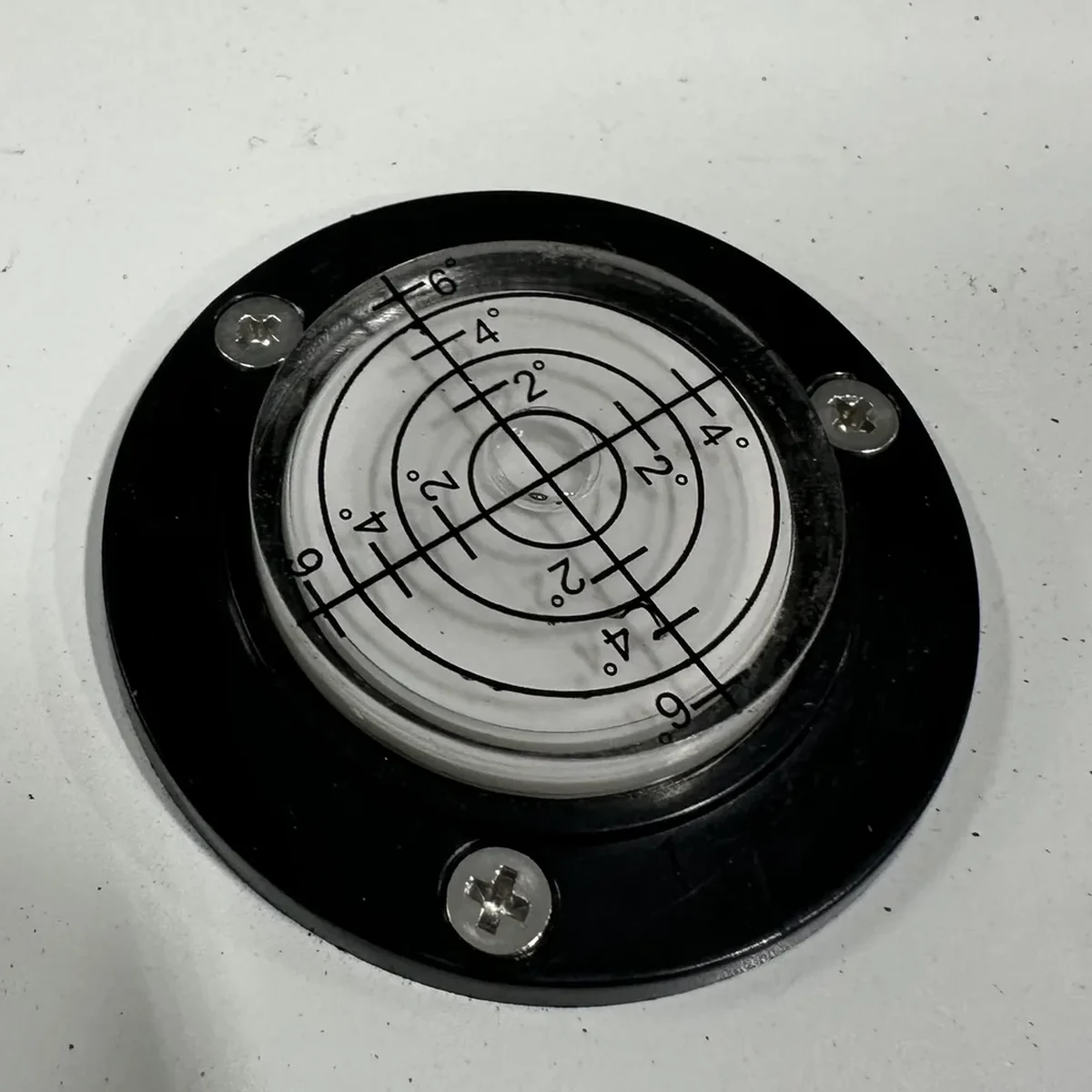
The trailer must be level with the outriggers extended before the mast is raised, and the outriggers must stay extended while it is up. Skipping this severely reduces stability and can let the mast tip and fall.
3. Slide the panels out
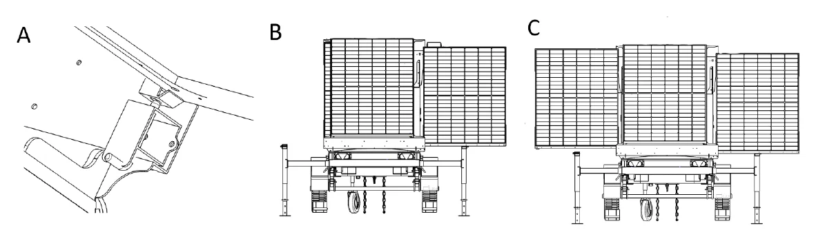
- Release the lock pin (A) and pull the panel rack out to its outermost position, until the lock snaps back in (B).
- Do the same on the other side. Both racks must be fully out and locked (C). The panel angle is fixed; there is nothing to tilt.
While charging, keep the panels facing the sun, unshaded, and clean. Never unplug a panel or a solar connector while the system is charging; it can injure you and damage the equipment.
4. Power up
- Unlock the equipment cabinet.
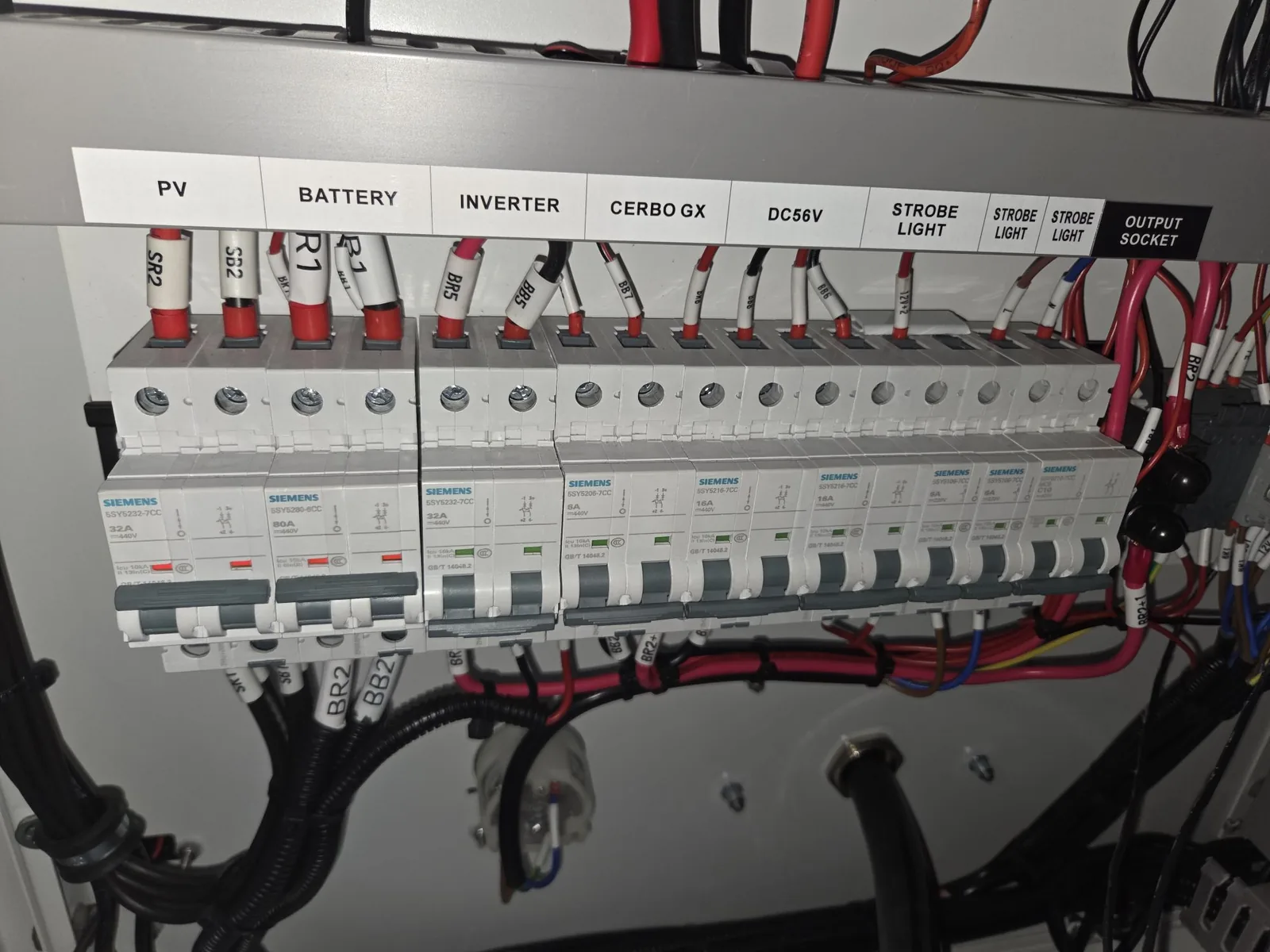
- Turn on the breakers for the solar panels (PV) and the battery, then the load breakers for the inverter, controller, and network. On these breakers a red indicator means on and green means off, the reverse of a house panel.
- Check the touch display shows solar input and battery voltage. It is inside the cabinet on the back wall, under a clear cover. The Power system page explains what you are looking at.
- Close and lock the cabinet.
The trailer is now live on the ground. Next: raise the mast.